

On this page
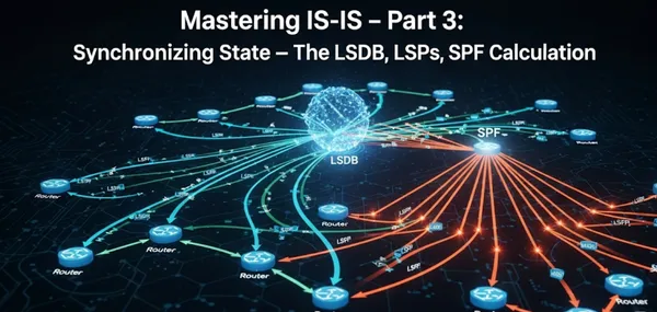
In the previous installments, we explored the theoretical foundation of IS-IS and then built a functional, multi-level IS-IS topology, complete with neighbor adjacencies and real Juniper CLI verification. Now, in Part 3, we enter the engine room of IS-IS: the Link-State Database (LSDB) and the processes that power it.
This is where topology information is stored, shared, and used to calculate optimal paths through the network. We’ll examine in detail how Link-State PDUs (LSPs) are originated, flooded, acknowledged, and aged. We’ll also dissect the Shortest Path First (SPF) algorithm and how it leverages this data to compute forwarding decisions. Along the way, we’ll touch on key topics like timers, route filtering, and administrative distance, which are all crucial for building a scalable and resilient network.
Reference Topology

Throughout this part, we will use the following multi-level IS-IS topology to illustrate key concepts and commands. This network features a Level 2 backbone connecting two separate Level 1 areas.
Key Components of the Reference Topology:
- Routers: The topology consists of four routers.
- Hierarchy: R1 and R3 form the Level 2 backbone. R2 and R4 are in separate Level 1 areas. R1 and R3 act as L1/L2 routers, connecting the levels.
- Area Addresses: The Level 2 backbone and the Level 1 area with R1 share the area address
49.0002.0000.0001.00. The Level 1 area with R4 uses the area address49.0003.0000.0004.00. - Adjacencies: There are two L1 adjacencies: one between R1 and R2, and another between R3 and R4. The L1-L2 adjacency between R1 and R3 forms the core of the Level 2 backbone.
- Loopback Prefixes: R4 has several loopback prefixes configured, which will be used in our examples for route filtering and summarization:
192.168.100.1/24,192.168.150.1/24,192.168.200.1/24, and192.168.250.1/24.
The LSDB: A Distributed Map of the Network
At its core, IS-IS is a distributed database protocol. Every IS-IS router maintains at least one Link-State Database (LSDB), with separate databases for Level 1 (intra-area) and Level 2 (inter-area) if the router is an L1/L2 device. This database is a collection of Link-State PDUs (LSPs) from every router in that area or level. Think of the LSDB as a comprehensive street map: it contains all the information about the roads (links), intersections (routers), and addresses (prefixes) within its domain.
Each router is responsible for originating its own LSP, which describes its unique attributes:
- Its own identity (System ID).
- The state of its directly connected links (up/down).
- The metric/cost of each link.
- The IP prefixes it originates.
- Its neighbors and their System IDs.
- Any special capabilities or information encoded in TLVs (e.g., MPLS TE, IPv6).
Dissecting the LSP Format
To truly understand the LSDB, you must understand the components of an LSP:
- LSP ID: A unique identifier for the LSP, composed of the router’s 6-byte System ID, a 1-byte Pseudonode ID (always 00 for a router's self-originated LSP), and a 1-byte LSP fragment number (e.g.,
R1.00-00). The fragment number is crucial for handling large topologies where a single LSP may exceed the maximum PDU size and must be split. - Sequence Number: A 4-byte number that is incremented with every new version of an LSP. This is the cornerstone of reliable flooding, as it ensures that routers always accept and propagate the newest version of a topology update, preventing stale information from being reintroduced.
- Checksum: A 2-byte field used to ensure the integrity of the LSP.
- Lifetime: A 2-byte field indicating how long the LSP is valid (default 1200 seconds). Routers periodically refresh their LSPs (by default every 900 seconds) to prevent them from expiring and being purged from the database.
- TLVs (Type-Length-Values): The payload of the LSP. This is where all the actual topology data is stored. As we discussed in Part 1, the modular nature of TLVs is what makes IS-IS so extensible.
Hello and Hold Timers: Maintaining Adjacencies
The stability of any IS-IS network relies on the reliable formation and maintenance of neighbor adjacencies. The Hello Timer and Hold Timer are the two key mechanisms that govern this process.
The Hello Timer (Hello Interval)
The Hello Timer is a periodic timer that dictates how often an IS-IS router sends out Hello PDUs on a given interface. The primary purpose of the Hello PDU is to discover and maintain adjacencies with neighboring routers.
- Purpose: Hello PDUs act as a "keepalive" mechanism. By sending them regularly, a router signals its presence and readiness to its neighbors.
- Default Values: The Hello Timer's default value depends on the link type: 10 seconds for broadcast interfaces and 3.3 seconds for point-to-point interfaces.
- Tuning: Decreasing the hello interval to values like 1 second or less (often called "fast hellos") can significantly speed up neighbor failure detection, leading to faster network convergence.
The Hold Timer (Hold Time)
The Hold Timer is a countdown timer that a router maintains for each of its IS-IS neighbors. When a router receives a Hello PDU from a neighbor, it resets this timer for that specific neighbor.
- Purpose: The Hold Timer acts as a "liveness" check. It determines how long a router will wait to receive a Hello PDU from a neighbor before considering that neighbor to be unreachable.
- Default Values: The Hold Time is typically a multiple of the Hello Timer, usually three times the hello interval.
- Function: If the Hold Timer for a neighbor expires, the router assumes the neighbor is down and tears down the adjacency. This event triggers an SPF calculation to find an alternative path, if one exists.
The two timers are intrinsically linked. When a router sends a Hello PDU, it includes its configured Hello Timer value. The receiving neighbor uses this value to calculate its Hold Timer for that adjacency (e.g., Hold Time = 3 * Hello Timer). This mechanism ensures both sides agree on the liveness check, providing a robust way to manage adjacency state.