On this page
The host is up and the images are in place (Part 2). Now the twelve switches boot, and a pile of disconnected boxes has to become a fabric. This part builds the underlay: the loopbacks, the point-to-point links, and the eBGP sessions that everything else in this series rides on. It also pays a debt from Part 1, where the diagram drew each leaf pair as one box and promised to show you the two switches inside. That is this post.
The underlay has exactly one job, and keeping that job small is the entire design: every switch loopback must be reachable from every other switch loopback. Nothing about tenants, nothing about VMs, no VXLAN yet. Just clean IP reachability, because Part 4 will build tunnels between those loopbacks and the tunnels do not care how the reachability happens, only that it does.
The shape of it
Two spines, ten leaves, and every leaf connects to both spines with a routed point-to-point link. No leaf-to-leaf links except inside a vPC pair, no spine-to-spine link at all. That absence surprises people who grew up on core-distribution designs, but it is the Clos property doing its work: any leaf reaches any other leaf in exactly one spine hop, and the two spines are two independent, equal-cost paths. A spine dies, the fabric loses half its capacity and none of its reachability.
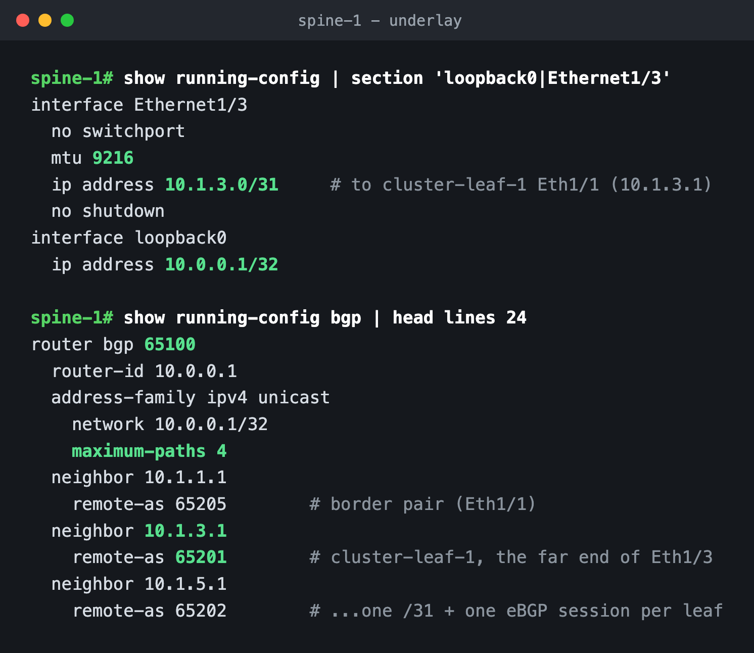
Addressing follows three rules I never break. Loopback0 is the router's identity: 10.0.0.1 and 10.0.0.2 for the spines, and the leaves numbered by role in decades, cluster leaves at 10.0.0.11 through .14, storage at .21 and .22, service at .31 and .32, border at .41 and .42, so a traceroute reads like a floor plan. Point-to-points burn /31s, not /30s, from a block per spine: 10.1.x.x for links to spine-1, 10.2.x.x for links to spine-2, so I can read a neighbor address and know which spine it faces. And every fabric interface runs MTU 9216, because VXLAN will add 50 bytes of headers in Part 4 and the underlay should never be the thing that fragments.
Here is spine-1's side of it, from the running config: