On this page
A GPU cluster that serves models has more than one kind of user. There is the team that runs it, there are the people inside the company who call its models, and sooner or later there is the public internet. The hard part of the network under that cluster is not any one switch. It is deciding which layer owns which decision: who may reach which model, where a gateway lives, what the rails are for, and how storage traffic stays off the paths that carry model traffic.
This post is the anatomy of such a fabric, taken from two complete builds. Both carry a Kubernetes cluster with an inference gateway, two user populations and an operator, enterprise storage and an out-of-band network. They differ in several places, and in the one this post is about: how the eight GPU rails are joined. Build A keeps the rails as plain VLANs with no routing at all; build B routes them over a leaf and spine fabric with eBGP. Everything below is as configured and as captured, with names made generic; the captures keep each platform's own syntax, because the design is what transfers.
The layers, in one pass
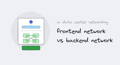
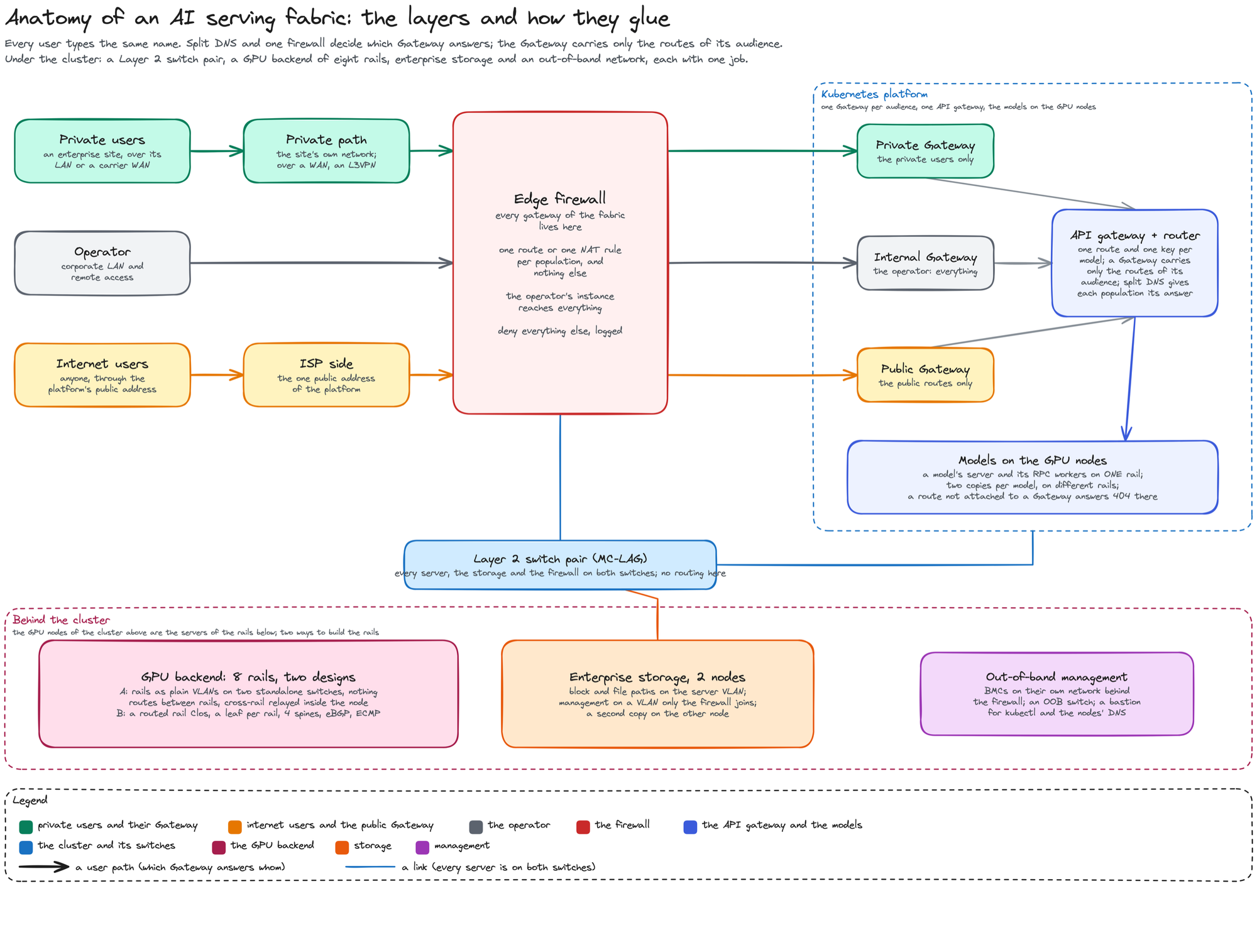
The edge: one firewall holds every gateway, and a population reaches its Gateway by one route in its own routing instance, or by one NAT rule keyed on its zone, and nothing else. The frontend: a Layer 2 switch pair with no SVI and no routing; every server, the storage and the firewall land on both switches, and every gateway is a tagged sub-interface of the firewall's bundle. The platform: one Gateway per audience, in front of an API gateway with one route and one key per model. The backend: eight rails, one interface per rail on every GPU node. Storage and out-of-band: two storage nodes with data in the server VLAN and management on a VLAN only the firewall joins; BMCs on their own network behind the firewall, on an out-of-band switch; a bastion in its own VLAN holds kubectl and the nodes' DNS.
The backend choice
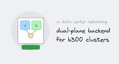
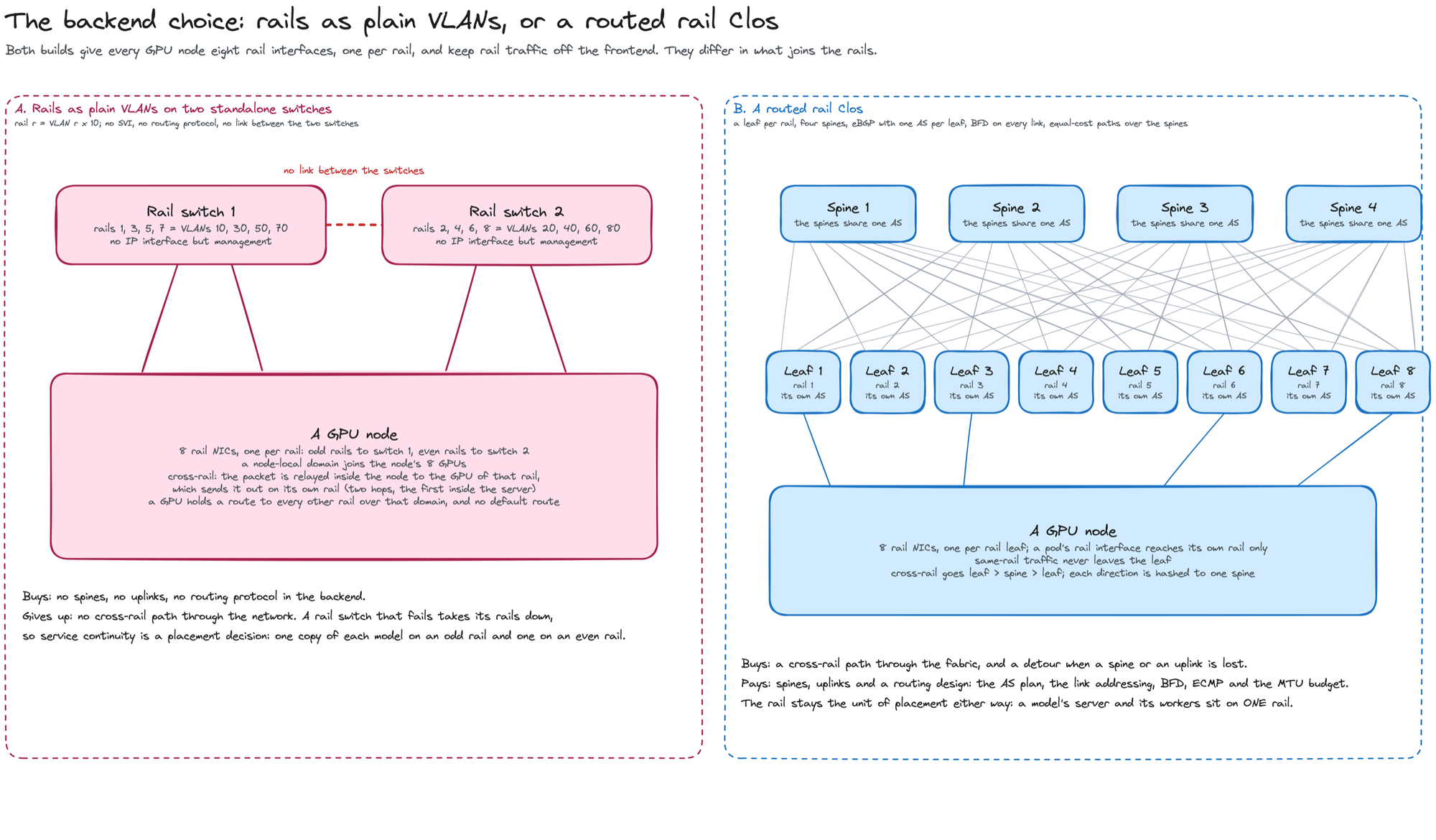
Build A deletes the spines. Rail r is VLAN 10r (rail 3 is VLAN 30) on one of two standalone switches, with no SVI, no routing protocol and no link between the switches, and a GPU reaches another rail by handing the packet to the GPU of that rail inside its own server, which sends it out on its own rail. Build B keeps the spines: a leaf per rail, four spines, eBGP with one AS per leaf and the spines sharing one, BFD on every link, equal-cost paths over the spines. Same-rail traffic never leaves the leaf; cross-rail traffic goes leaf, spine, leaf. The rest of this post walks each layer with its configuration and shows what each backend asks of the node and the pod.
The book behind this fabric
The reasoning behind every layer here is worked out, with labs you can build yourself, in my book BGP for AI Infrastructure: A DevOps Engineer's Guide to AI Data Center Fabric Networking: the frontend and backend split in chapters 3 and 4, rail topologies and the eBGP underlay in chapters 5 and 6, how a Gateway's address is announced, and the edge, in chapters 11 and 12, storage in chapter 14. It is on Amazon in paperback and Kindle: BGP for AI Infrastructure on Amazon.
Below the line: each layer as configured and captured, and both backends in their own words.