

On this page
Welcome back to the Mastering IS-IS series. In our first post, we deconstructed the fundamental building blocks of IS-IS, exploring its historical context, unique Layer 2 operation, NSAP addressing, and extensible TLV architecture. We laid the theoretical groundwork for why IS-IS is the protocol of choice for large-scale, resilient networks.
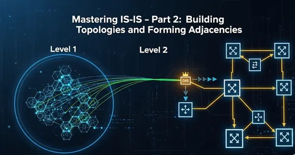
In this second part, we move from theory to practice, delving into the dynamic heart of the protocol: how routers discover each other, form adjacencies, and synchronize their link-state databases. We’ll dissect the roles of the Designated Intermediate System (DIS) and the nuances of different network types. Most importantly, we'll build a practical, multi-level IS-IS topology and use real-world Juniper CLI commands to verify our configurations and truly see the protocol in action.
Adjacency Formation: The Foundation of a Link-State Network
Before a router can share topology information, it must first discover its neighbors. IS-IS, like OSPF, uses Hello PDUs (Protocol Data Units) for this purpose. The Hello PDU, known as an IIH (IS-IS Hello), is the handshake that establishes and maintains a neighbor relationship, or adjacency.
The adjacency process depends critically on the network type. IS-IS classifies network interfaces into two types:
- Point-to-Point (P2P): A direct, one-to-one link between two routers (e.g., a serial link or an Ethernet link explicitly configured as P2P). Only one Hello PDU type is exchanged (PDU Type 17). Optionally, a three-way handshake using TLV 240 can enhance reliability by confirming bidirectional reachability and ensuring symmetric visibility. In the output below you will see that no DR is elected and the interface is point to point
root@R1# run show isis interface ge-0/0/1.0 extensive
IS-IS interface database:
ge-0/0/1.0
  Index: 342, State: 0x6, Circuit id: 0x1, Circuit type: 2
  LSP interval: 100 ms, CSNP interval: 5 s, Loose Hello padding, IIH max size: 1492
  Adjacency advertisement: Advertise, Layer2-map: Disabled
  Interface Group Holddown Delay: 20 s, remaining: 0 s
  Level 1
    Adjacencies: 0, Priority: 64, Metric: 10
    Disabled
  Level 2
    Adjacencies: 1, Priority: 64, Metric: 10
Hello Interval: 9.000 s, Hold Time: 27 s- Broadcast: A multi-access network segment where multiple routers can exist (e.g., a traditional Ethernet LAN). Adjacencies are established after three-way communication is confirmed by verifying the IS Neighbors TLV (Type 6). All routers form adjacencies with each other, but only one is elected as the Designated Intermediate System (DIS) to manage flooding on the LAN. Routers send Level 1 and/or Level 2 Hellos to multicast MACs: L1:
01-80-C2-00-00-14and L2:01-80-C2-00-00-15
root@R1# run show isis interface ge-0/0/1.0 extensive
IS-IS interface database:
ge-0/0/1.0
  Index: 342, State: 0x6, Circuit id: 0x1, Circuit type: 2
  LSP interval: 100 ms, CSNP interval: 10 s, Loose Hello padding, IIH max size: 1492
  Adjacency advertisement: Advertise, Layer2-map: Disabled
  Interface Group Holddown Delay: 20 s, remaining: 0 s
  Level 1
    Adjacencies: 0, Priority: 64, Metric: 10
    Disabled
  Level 2
    Adjacencies: 1, Priority: 64, Metric: 10
    Hello Interval: 9.000 s, Hold Time: 27 s
    Designated Router: R3.02 (not us)
The Adjacency Handshake on a P2P Link
On a P2P link, the process is straightforward. Each router sends IIHs to a multicast address (01-80-C2-00-00-15 for L2 Hellos). When a router receives an IIH from a potential neighbor, it adds that router to its list of neighbors. The adjacency is fully established once they both receive IIHs from each other and key parameters (area ID, level type, authentication) match. There is no election process; the two routers simply form a direct adjacency.
The Adjacency Handshake on a Broadcast Link
The process is more complex on a broadcast network to prevent an "adjacency explosion," where every router forms a full adjacency with every other router on the segment. To manage this, IS-IS elects a Designated Intermediate System (DIS).
The DIS is not a full-time "master" like OSPF's DR/BDR; its role is primarily to simplify the topology and facilitate database synchronization.
The Role of the Designated Intermediate System (DIS)
The DIS performs two key functions:
- Topology Simplification: The DIS acts as a pseudonode for the broadcast segment. All routers on the segment form an adjacency with the DIS, and the DIS, in turn, advertises the segment's prefixes and other routers into the LSDB. This prevents a full mesh of adjacencies, which would create a more complex topology graph for the SPF algorithm to compute.
- Database Synchronization: The DIS is responsible for periodically multicasting Complete Sequence Number PDUs (CSNPs), which provide a summary of all LSPs in the LSDB for that level. This helps ensure all routers on the segment have a consistent view of the topology.
The DIS election is based on a configured priority. The router with the highest priority wins. In the case of a tie, the router with the highest System ID wins.
Tip: You can influence DIS election by setting interface priorities. Use a priority of 0 to make a router ineligible for election.
Dissecting the IS-IS Database: The Topology Map
The heart of any link-state protocol is its database. In IS-IS, this is the Link State Database (LSDB), which stores all the LSPs flooded throughout an area or level. Interpreting this database is a key skill for any network engineer.
On a Juniper, From operational mode, enter the show isis interface command.